LPG recovery using refrigeration loop
Process modeling and simulation with ProSimPlus
|
|
|
The model
The objective of this process is to recover LPG (liquefied petroleum gases) with a fixed mass-fraction of methane, from a gas mixture. The main LPG components are hydrocarbons (mainly in the C3-C4 range), propane and butane.
The process utilizes a closed propane refrigeration loop (green streams) around a brazed plate fin heat exchanger.
The description of the process follows.
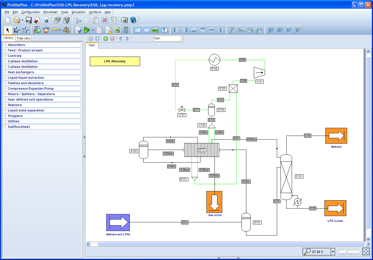
The initial gas mixture (Methane and LPGs) is sent in a two-phase separator (S101) in order to eliminate the heaviest compounds which are sent to the distillation column (C101). The others leave at the top of the vessel and are cooled in the brazed plate fin heat exchanger (E101). They are then forwarded in another two-phase separator (S102) to separate heavy and lights. The two output streams (stream C03in and C04in) are sent back in the plate-fin heat exchanger as cold streams.
Once treated, the gas is mainly composed of methane and ethane and flows out of the exchanger (stream C04out).
This gas, not entirely liquefied, is sent in a deethanizer column (C101), like the bottom stream of the first two-phase separator (C14).
This column is set to recover at the bottom, a liquid having a minimal, specified mass-fraction of methane (0.05 lb/h).
Refrigeration loop
The main cold streams of the plate-fin heat exchanger are the two propane streams (C05out and C06out).
On the outlet side of the plate-fin heat exchanger, they are mixed and sent in a compressor (K101) which increases their pressure and their temperature. The heat generated is recovered in an exchanger (E102).
Propane then flows in an expansion valve (v101) in order to decrease its pressure. A liquid-gas mixture is formed and sent in a separator (S104). Liquid propane is returned in the plate-fin heat exchanger (streams C05in and C06in). The gas propane (stream C12) is mixed with hot streams of propane leaving the brazed plate fin heat exchanger (E101).
Propane circulates in closed loop in the system where it acts as a refrigerant.
Heat exchanger description
This process implements a brazed plate-fin heat exchanger (E101). Only one of these exchangers can contain more than ten different hot and cold streams.
Thanks to its low cost of production and its high performances (they are generally made of brazed aluminum), it is increasingly used in cryogenic processes.
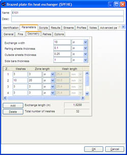
The model implemented in ProSimPlus is a detailed model which takes into account all the complexity of the geometry of this type of exchangers.
The single assumption made is of a common wall temperature off stacking (known as TPC assumption).
Another ProSim software, ProSec, makes it possible to bypass this assumption for even more accurate calculations.
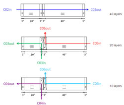
The exchanger is composed of three references paths, shared by the hot and cold streams. The main stream (C02) flows throughout the heat exchanger, the secondary streams are withdrawn (C05, C06) or fed (C03, C04) on the side of the unit.
|
|
The figures below present the fins used for the several flow paths in the heat exchanger as well as their topology (exchange, distribution and dead zones). Only one fin is used in this example (Fin #2873 from Fives Cryo (formerly called Nordon Cryogénie)):
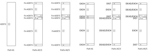
|
Components
Components taken into account in the simulation are extracted from the ProSimPlus standard database:
| Name | Chemical formula |
| Nitrogen | N2 |
| Methane | CH4 |
| Ethane | C2H6 |
| Propane | C3H8 |
| Isobutane | C4H10 |
| n-Butane | C4H10 |
| Isopentane | C5H12 |
| n-Pentane | C5H12 |
| n-Hexane | C6H14 |
| n-Heptane | C7H16 |
Thermodynamic model
The thermodynamic model is based on an equation of state approach. The chosen equation of state is the Peng Robinson (PR) equation with binary interaction parameters extracted from the ProSimPlus database.
|
ADDITIONAL INFORMATION
Contact ProSim by e-mail (sales @ prosim.net) or through the contact page from ProSim website (click on the button):

|
|
|
|


